Pedal Power: Difference between revisions
Ted Moallem (talk | contribs) No edit summary |
No edit summary |
||
| (24 intermediate revisions by 3 users not shown) | |||
| Line 5: | Line 5: | ||
The goal for this design was low cost, with most materials sourced from Home Despot and/or local hardware stores. Can be built relatively easily by anyone with access to drill press and basic tools. Circuitry includes voltage regulator ($1.50 from digikey), a few capacitors/resistors, and a diode. | The goal for this design was low cost, with most materials sourced from Home Despot and/or local hardware stores. Can be built relatively easily by anyone with access to drill press and basic tools. Circuitry includes voltage regulator ($1.50 from digikey), a few capacitors/resistors, and a diode. | ||
[[File:Pedalpower.jpg]] | |||
'''<span style="color:#ff0000;"> | '''<span style="color:#ff0000;">10/28/12: UPDATE IN PROGRESS</span>''' | ||
Also check out:<br /> | |||
[http://pedalpower2thepeople.pbworks.com/w/page/47830717/FrontPage pedalpower2thepeople.pbworks.com] and | |||
[http://www.youtube.com/watch?feature=player_embedded&v=dDUWduvdhL4 video] | |||
__TOC__ | __TOC__ | ||
| Line 22: | Line 22: | ||
List admin: [mailto:moallem@mit.edu?subject=OB%20PedalPower%20Documentation moallem@mit.edu] | List admin: [mailto:moallem@mit.edu?subject=OB%20PedalPower%20Documentation moallem@mit.edu] | ||
<p style="text-align: center;"></p><p style="text-align: center;">(** PLEASE DO NOT RELOCATE OR RADICALLY MODIFY THIS PAGE WITHOUT FIRST CONTACTING LIST ADMIN. KTHX **)</p> | <p style="text-align: center;"></p><p style="text-align: center;">(** PLEASE DO NOT RELOCATE OR RADICALLY MODIFY THIS PAGE WITHOUT FIRST CONTACTING LIST ADMIN. KTHX **)</p> | ||
== Parts/Materials List == | == Parts/Materials List == | ||
<p style="text-align: center;">''<span style="font-size:larger;">"A-frame" bicycle stand</span>''</p> | <p style="text-align: center;">''<span style="font-size:larger;">"A-frame" bicycle stand</span>''</p> | ||
| Line 29: | Line 28: | ||
'''TWO (2) x''' <u>'''20" lengths of 1" x 1" (cross-section) rectangular steel tubing'''</u> | '''TWO (2) x''' <u>'''20" lengths of 1" x 1" (cross-section) rectangular steel tubing'''</u> | ||
*e.g., | *e.g., [http://www.homedepot.com/h_d1/N-5yc1v/R-202183567/h_d2/ProductDisplay?langId=-1&storeId=10051&catalogId=10053 http://www.homedepot.com/h_d1/N-5yc1v/R-202183567/h_d2/ProductDisplay?langId=-1&storeId=10051&catalogId=10053] | ||
*Alternatively, can use up to 2" x 1" (cross-section) rectangular steel tubingfor added stability | *Alternatively, can use up to 2" x 1" (cross-section) rectangular steel tubingfor added stability | ||
| Line 36: | Line 35: | ||
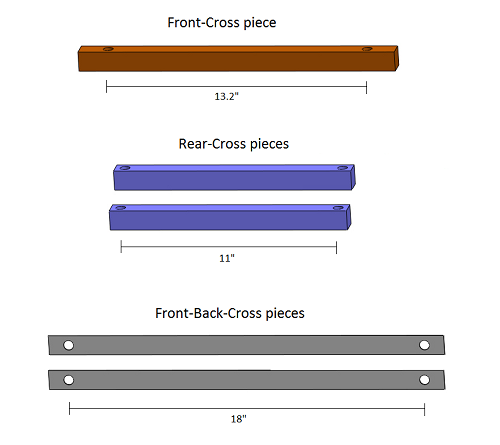
Rear-Cross piece: | Rear-Cross piece: | ||
'''TWO (2) x''' '''<u>12" lengths of 1" x 1" rectangular steel tubing</u> ''' | '''TWO (2) x''' '''<u>12" lengths of 1" x 1" rectangular steel tubing</u> ''' | ||
*Alternatively, can use single piece of 2" x 1" rectangular steel tubing | *Alternatively, can use single piece of 2" x 1" rectangular steel tubing | ||
| Line 62: | Line 60: | ||
Front-Back-Cross pieces: | Front-Back-Cross pieces: | ||
'''TWO (2) x''' 20" | '''TWO (2) x''' <u>'''20" lengths of flat steel bar''' </u> | ||
*e.g., | *e.g., [http://www.homedepot.com/h_d1/N-5yc1v/R-202183541/h_d2/ProductDisplay?langId=-1&storeId=10051&catalogId=10053 http://www.homedepot.com/h_d1/N-5yc1v/R-202183541/h_d2/ProductDisplay?langId=-1&storeId=10051&catalogId=10053] | ||
| Line 75: | Line 73: | ||
<br/>____________________ | <br/>____________________ | ||
<p style="text-align: center;"><span style="font-size:larger;">''Rear-wheel (skewer) supports:''</span></p> | <p style="text-align: center;"><span style="font-size:larger;">''Rear-wheel (skewer) supports:''</span></p> | ||
'''TWO (2) x <u>6" lengths of 3/4 | '''TWO (2) x'''<u>'''5"-6" long fully-threaded bolts, size 3/4-10 (standard)'''</u> | ||
*bolt head type does not matter | |||
*Alternatively, can use 5"-6" lengths of 3/4-10 threaded rod | |||
'''FOUR (4) x <u>3/4-10 Hex Nuts</u>''' | |||
'''''TWO (2) x ''<u>1/2 in. PVC Sch. 40 Pressure Slip x FIPT Female Adapter </u>''' | |||
*e.g., [http://www.homedepot.com/h_d1/N-5yc1v/R-100087245/h_d2/ProductDisplay?selectedCatgry=SEARCH+ALL&jspStoreDir=hdus&catalogId=10053&navFlow=3&keyword=435-005&Ntpc=1&langId=-1&Nu=P_PARENT_ID&storeId=10051&Ntpr=1&ddkey=Search http://www.homedepot.com/h_d1/N-5yc1v/R-100087245/h_d2/ProductDisplay?selectedCatgry=SEARCH+ALL&jspStoreDir=hdus&catalogId=10053&navFlow=3&keyword=435-005&Ntpc=1&langId=-1&Nu=P_PARENT_ID&storeId=10051&Ntpr=1&ddkey=Search] | |||
'''TWO (2) x <u>Hose clamps</u> [OPTIONAL]''' | |||
*'''Hose clamps are optional --- to reinforce PVC adapter cups, if desired''' | |||
*e.g., [http://www.homedepot.com/h_d1/N-5yc1v/R-202309385/h_d2/ProductDisplay?langId=-1&storeId=10051&catalogId=10053 http://www.homedepot.com/h_d1/N-5yc1v/R-202309385/h_d2/ProductDisplay?langId=-1&storeId=10051&catalogId=10053] | |||
____________________ | ____________________ | ||
<p style="text-align: center;"><span style="font-size:larger;">''Generator and mounting assembly:''</span></p> | <p style="text-align: center;"><span style="font-size:larger;">''Generator and mounting assembly:''</span></p> | ||
[http://www.youtube.com/embed/mCI_Ke1tA4o What_kind_of_motor_should_I_use?] | |||
'''ONE (1) x''' 24V DC motor (100 to 350 watt) | '''ONE (1) x''' 24V DC motor (100 to 350 watt) | ||
| Line 97: | Line 116: | ||
<span style="background-color:#ffff00;">[SPECIFY BRACKETS, FASTENER HARDWARE, AND DISTAL ROLLER SUPPORT!!! ]</span> | <span style="background-color:#ffff00;">[SPECIFY BRACKETS, FASTENER HARDWARE, AND DISTAL ROLLER SUPPORT!!! ]</span> | ||
| Line 122: | Line 140: | ||
*'''IMPORTANT''': Depending on circuit configuration, it may be necessary to connect diode and voltage regulator to <u>separate, non-contacting heat sinks</u>. (Remember, aluminum conducts electricity!) | *'''IMPORTANT''': Depending on circuit configuration, it may be necessary to connect diode and voltage regulator to <u>separate, non-contacting heat sinks</u>. (Remember, aluminum conducts electricity!) | ||
<div><br/></div> | <div><br/></div> | ||
== Construction == | |||
https://lh6.googleusercontent.com/-M0YutxOAK3s/TtR7D7fCEfI/AAAAAAAAAaY/Jdd2c0nbg6c/s700/PedalGen_Assem1-1_crop_labeled_small.png | |||
'''Basic A-frame configuration, depicted without nut/bolt fasteners.''' | |||
---- | |||
https://lh3.googleusercontent.com/-83bUPHfVsQo/TtR_DKo-MYI/AAAAAAAAAaw/drxq-OJgBk4/s550/Rear-legs1_labeled_small.png | |||
*On one face of each rear leg piece, mark distances of 1.5" and 2.5" from bottom edge, centered along the width. Drill two through-holes, slightly larger than fastening bolt diameter. | |||
*On perpendicular face of each rear leg piece, mark distances of 4", 16.5", and 18" from bottom edge, centered along the width. | |||
*At 4" and 16.5" marks, drill through-holes, slightly larger than bolt diameter. | |||
*At 18" mark, drill though-hole of approximately 0.75" diameter (to fit size 3/4-10 bolt or threaded rod). | |||
---- | |||
https://lh4.googleusercontent.com/-cUNN0LFpU0g/TtR6nMlXC_I/AAAAAAAAAaQ/Gzwcfl9tY3Q/s500/Front-legs1_labeled_small.png | |||
*If using angle steel, note that hole patterns of the two front legs are mirror images of one another. | |||
*On one face of each front leg piece, mark distance of 1.5" from bottom edge, centered along the inner-face width. Drill through-hole slightly larger than fastening bolt diameter. | |||
*On perpendicular face of each front leg piece, mark distances of 3" and 18" from bottom edge, centered along the inner-face width. Drill through-holes slightly larger than fastening bolt diameter. | |||
---- | |||
https://lh4.googleusercontent.com/-uSEy3Wg2K1g/TtR-oJgzGiI/AAAAAAAAAao/fjkx256U198/s500/Cross-pieces1_labeled_small.png | |||
== Operation == | |||
[[Category:Working groups]] | |||
Latest revision as of 12:59, 5 November 2012
Pedal Power for the Occupy Movement
To support the self-sufficiency of Occupy member sites, the Pedal Power group aims to facilitate the low-cost construction and effective usage of pedal-powered electrical generators and related technologies.
The goal for this design was low cost, with most materials sourced from Home Despot and/or local hardware stores. Can be built relatively easily by anyone with access to drill press and basic tools. Circuitry includes voltage regulator ($1.50 from digikey), a few capacitors/resistors, and a diode.

10/28/12: UPDATE IN PROGRESS
Also check out:
pedalpower2thepeople.pbworks.com and
video
Contact Info
Group email: pedalpower@mit.edu
List admin: moallem@mit.edu
(** PLEASE DO NOT RELOCATE OR RADICALLY MODIFY THIS PAGE WITHOUT FIRST CONTACTING LIST ADMIN. KTHX **)
Parts/Materials List
"A-frame" bicycle stand
Rear Legs:
TWO (2) x 20" lengths of 1" x 1" (cross-section) rectangular steel tubing
- e.g., http://www.homedepot.com/h_d1/N-5yc1v/R-202183567/h_d2/ProductDisplay?langId=-1&storeId=10051&catalogId=10053
- Alternatively, can use up to 2" x 1" (cross-section) rectangular steel tubingfor added stability
Rear-Cross piece:
TWO (2) x 12" lengths of 1" x 1" rectangular steel tubing
- Alternatively, can use single piece of 2" x 1" rectangular steel tubing
Front Legs:
TWO (2) x 20" lengths of 1-inch angle steel
- e.g., http://www.homedepot.com/h_d1/N-5yc1v/R-202183502/h_d2/ProductDisplay?langId=-1&storeId=10051&catalogId=10053
- Alternatively, can use 20" lengths of 1" x 1" rectangular steel tubing
Front-Cross piece:
ONE (1) x 16" length of 1" x 1" rectangular steel tubing
- For extra stability, lengthen FRONT-CROSS piece to between 20"-30", and add rubber feet at either end
Front-Back-Cross pieces:
TWO (2) x 20" lengths of flat steel bar
Nuts and Bolts:
- Use bolts sized 10mm to 12mm (standard sizes 3/8, 7/16, or 1/2), 'with correspondingly sized nuts, unless otherwise specified.
- Drill holes to slightly larger diameter than that of traversing bolt.
____________________
Rear-wheel (skewer) supports:
TWO (2) x5"-6" long fully-threaded bolts, size 3/4-10 (standard)
- bolt head type does not matter
- Alternatively, can use 5"-6" lengths of 3/4-10 threaded rod
FOUR (4) x 3/4-10 Hex Nuts
TWO (2) x 1/2 in. PVC Sch. 40 Pressure Slip x FIPT Female Adapter
TWO (2) x Hose clamps [OPTIONAL]
- Hose clamps are optional --- to reinforce PVC adapter cups, if desired
- e.g., http://www.homedepot.com/h_d1/N-5yc1v/R-202309385/h_d2/ProductDisplay?langId=-1&storeId=10051&catalogId=10053
____________________
Generator and mounting assembly:
What_kind_of_motor_should_I_use?
ONE (1) x 24V DC motor (100 to 350 watt)
ONE (1) x heavy-duty door hinge
ONE (1) x strong L-bracket, at least 3" long on one side
TWO (2) x mounting plates (approx. 5" x 5", either steel or thick aluminum)
ONE (1) x roller bearings (should fit motor shaft perfectly)
ONE (1) x roller: solid aluminum cylinder, 1.25" to 1.5" diameter (Note: Can alternatively use Nylon cylinder with thin aluminum pipe as sheath)
[SPECIFY BRACKETS, FASTENER HARDWARE, AND DISTAL ROLLER SUPPORT!!! ]
____________________
Electronics:
ONE (1) x low-voltage schottky diode
- e.g., http://search.digikey.com/us/en/products/SR1045-TP/SR1045-TPMSCT-ND/2334476
- e.g. (alt), http://search.digikey.com/us/en/products/MBR1645G/MBR1645GOS-ND/918588
- Note: Regular diode will work, but schottky diode minimizes power loss
ONE (1) x adjustable positive voltage regulator
- e.g., 5-Amp low dropout (LDO) linear voltage regulator: http://search.digikey.com/us/en/products/LD1084V/497-3413-5-ND/669183 [LD1084V Datasheet]
- e.g. (alt), 7.5-Amp LDO linear voltage regulator: http://search.digikey.com/us/en/products/LT1083CP%23PBF/LT1083CP%23PBF-ND/888922 [LT1083 Datasheet]
- Note: Appropriate adjustment of maximum output voltage commonly requires several additional electronic components, as specified in voltage regulator datasheet. For the LD1084V regulator used below, the required components are two capacitors (both 10 uF) and two resistors (120 Ω and 1.2 kΩ)
Two (2) x aluminum heat sinks
- Can use scrap aluminum bar or thick sheeting, so long as there is a flat surface for mounting to components
- IMPORTANT: Depending on circuit configuration, it may be necessary to connect diode and voltage regulator to separate, non-contacting heat sinks. (Remember, aluminum conducts electricity!)
Construction
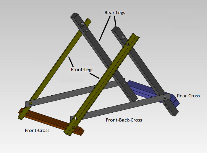
Basic A-frame configuration, depicted without nut/bolt fasteners.

- On one face of each rear leg piece, mark distances of 1.5" and 2.5" from bottom edge, centered along the width. Drill two through-holes, slightly larger than fastening bolt diameter.
- On perpendicular face of each rear leg piece, mark distances of 4", 16.5", and 18" from bottom edge, centered along the width.
- At 4" and 16.5" marks, drill through-holes, slightly larger than bolt diameter.
- At 18" mark, drill though-hole of approximately 0.75" diameter (to fit size 3/4-10 bolt or threaded rod).

- If using angle steel, note that hole patterns of the two front legs are mirror images of one another.
- On one face of each front leg piece, mark distance of 1.5" from bottom edge, centered along the inner-face width. Drill through-hole slightly larger than fastening bolt diameter.
- On perpendicular face of each front leg piece, mark distances of 3" and 18" from bottom edge, centered along the inner-face width. Drill through-holes slightly larger than fastening bolt diameter.